By John Blyler, JB Systems and Bill Chown, Siemens Mentor Graphics
Most engineers would prefer to do design work than spend much time on the often onerous task of requirements identification, derivation and allocation. The sooner they are given the relevant requirements, the sooner they can begin the work for which most engineers in the traditional domains have been educated–namely, design and development.
The problem is that rushing the requirements process and not fully appreciating the actual problem to be solved will doom most projects to an endless cycle of costly and time-consuming do overs.
It’s time that we step back and apply the forgotten methodology of, and tools for, developing a system context before jumping into the requirements activity. The approach is particularly relevant and has gained renewed interest with the emergence of system-of-systems (SoS) designs, especially in multiple operational environments.
This paper will review the basic approach, techniques and tools for developing a system context.
Elements of the System Context
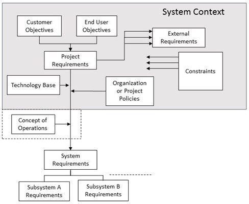
The system context is used to define the problem (see Figure 1). It is developed before the system requirements are defined, typically in the conceptual design phase of a project. Note that, while most elements are input to the “Project Requirements,” the “External Requirements” are not. External requirements are things we require of external agencies (more on that shortly). In contrast, constraints are things imposed upon the product or the system.
The dotted lines around the Concept of Operations (ConOps) document indicates that it may or may not be an element of the system concept. It is shown outside the context as it typically is developed by systems engineers to start the generation of the system requirements. In practice, it is often not used until problems arise in the system requirements development process and the need for it is realized.
Now let’s consider the key elements that make up the system context. It is important that the systems engineer ensures that the customer (or project manager) and the end user (if accessible) have a common understanding of the objectives or marketing definition of the needed system. Achieving this understanding is often hard work that requires many iterations before an agreement is reached. Once reached, this task will also help set the priorities for the work that will follow.
The end results of creating a system context are a high level set of project requirements and perhaps some specific policies defined by the project manager to guide the development process.
It should be noted that the “Customer or Sponsor” and the “User” form only the minimum of initial high-level inputs to the “Project Requirements.” Other important players may include stakeholders or those people affected by the system and the decision makers. The latter must choose from among many different options using a particular (and not always apparent) system of metrics.
Next let’s look at organizational and project policies. Organizational policies shape everything from the mix of contract verse company employees to the development process standards that will be used. These policies may often set the minimum acceptable standards for non-functional requirements like reliability, availability, maintainability, safety, security, etc. Product compatibility and warranty standards may also be affected by organizational polities.
Project-unique policies typically address the minimum programmatic and technical resource reserves in various phases of the product life cycle. Project policies set the make verses buy criteria as well as guidance for product quality trade-offs. Project policies often set the agenda topics for any formal phase-related reviews.
The problem with policies is that they tend to influence the development process and tend to increase in number with time. Further, customer priorities tend to change, thus influencing the policies. Finally, policies can handicapped a project due to vagueness. Here is but one example: “No single fault shall cause a loss of the capability to accomplish the prime mission objectives.”
Constraints are a critical part of the system context. Constraints may relate to inherited hardware or software, or the requirement to or restriction on using certain technologies. The organizational structure of a company and its skill base also place constraints on what products can be build. Of course, cost and schedule impose constraints on the system.
Constraints often represent deeply entrenched decisions and preferences. One example might be a constraint to use a specific legacy hardware device or software application. An example of technology requirements might be the use of a specific programming language. Inhibiting technologies might include the use of certain types of materials for structures or environmentally related concerns.
External requirements relate to the requirements of others. These are things imposed upon other agencies by your system or product. For example, external requirements might be imposed on the manufacturing department. The engineers might decide to implement a design using surface-mount chip technology but the company’s manufacturing assembly line doesn’t have that capability. This external requirement will either cause the manufacturing department to develop the capability to perform surface-mounted implementation or result in negotiations for a more viable solution with the engineering department.
Often, external requirements occur at the interface. For example, interfacing systems may have to change to correctly interface with a new system under design – one which you have under your control. Such requirements are important to identify and keep visible as they serve as a dependency that affects the implementation of other systems.
People often confuse external requirements and constraints. The former are applied by your project and affect other systems. The latter serve as restrictions on your project from other systems.
Project requirements are the initial, top-level interpretation of the customer and user objectives. These requirements must be matched to available project resources and schedule, which is typically the role of the project manager with input from system engineering support.
The project requirements are derived from customer-user objectives as influenced and constrained by the other aspects of the system context. These requirements are usually a jumble of quantitative statements containing a few objectives. The systems engineer must prioritize the project requirements based upon the customer-user objectives and organization-project policies.
Gibson’s Rule Number 3
In 1990, a systems analyst named Jack Gibson condensed his very useful experiences into a list of ten rules to aid in the practice of systems engineering. In addition to being good heuristics, these rules help one appreciate what the systems approach is really all about and why it is different from the traditional approach to engineering [1]. This point will become obvious later in this paper.
Out of these ten rules, one stands out as being directly applicable to the creation of a system context:
- Rule #3: You Must Generalize the Problem to give it Contextual Integrity.
The key challenge in dealing with a customer-user is to truly understand the original problem they are trying to solve, i.e., to ensure the integrity of the problem context. Earlier in his work, Gibson introduces the technique of active listening to aid in this task of getting to the root of the problem. But to do so, you must first understand the context of the customer’s or client’s problem. If, as a system analyst, you skip this step, then you will likely miss some of the important aspects of the problem. Gibson emphasized that this understanding of the customer’s real problem is one of the things that makes the system engineering approach to problem solving different from traditional engineering.
In domain-specific or traditional engineering, the design goal is to abstract and isolate a problem from its context and divide it up in to smaller manageable parts that can then be analyzed and constructed – e.g., as hardware or software components. These component parts are then integrated and tested into the final end product. This bottom-up approach of working from the specific to the more general works best with well-defined problems that have well-known and established solution procedures. This is the realm of the fundamental engineering domains like electrical, mechanical, civil, aerospace, chemical, or industrial engineering. For more complex, ill-defined problems with unknown solution procedures, Gibson recommends a top-down approach.
In Gibson’s vision of the top-down approach, you move up one or two levels by generalizing the original problem statement so you understand it better in light of a broader context. Next, you resolve the problem by proceeding from the general to the more specific case. As an example of this approach, Gibson relates his work on a proposed subway system in the city of Detroit. The city requested inputs on whether to build an expensive new 4.5 mile subway line. The bottom-up approach would have started with that goal and immediately subdivided the proposed 4.5 mile subway into smaller sections. Each section would have been examined in terms of design and implementation difficulties and the associated cost and schedule.
Conversely, the top-down approach first extended the 4.5 mile question to look at a longer subway to serve beyond the 4.5 mile line. The system analysts generalized the original problem statement to several levels up. This allowed them to examine Detroit’s major arterial transportation needs. In so doing, they discovered that the city’s real problem was growing traffic congestion in downtown Detroit, which would not have been solved with the 4.5 mile extension. This was only discovered by a top-down approach.
Naturally, there are limits to the top-down approach. Gibson warns that one should be careful not to generalize the customer’s problem too far as even a simple problem can become too difficult or costly to solve if over-generalized. The intention is to ensure one is solving the right problem.
System Context Modeling
A graphical model of the system context helps to visualize the many interfaces that shape the problem. A system context diagram must show a system and its inputs and outputs.
According to Kossiakoff and Sweet (2011) [2]: “System Context Diagrams… represent all external entities that may interact with a system… Such a diagram pictures the system at the center, with no details of its interior structure, surrounded by all its interacting systems, environments and activities. The objective of the system context diagram is to focus attention on external factors and events that should be considered in developing a complete set of systems requirements and constraints.”
System context diagrams are used early in a project to get agreement on the things influencing the potential solution of a problem [3]. Context diagrams are typically included in a requirements document. These diagrams must be read by all project stakeholders and thus should be written in plain language, so the stakeholders can understand items within the document.
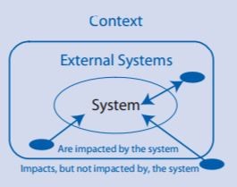
IBM references a diagram from Buede [4] in their description of developing a system context (see Figure 2). They assert that, when presented with a system design problem, the systems engineer’s first task is to truly understand the problem and its context. As explained earlier, a context diagram is a useful tool for understanding the system to be built and the external domains and interfaces that are relevant to that system.
In Figure 2, the system is surrounded by the external systems which have interfaces to the system under design. These external systems interact with the system via the system’s external interfaces. Some of these external systems impact but are not impacted by the system. In our earlier discussion, these external systems would act as constraints on the system.
There are other types of context diagrams that are used in both systems and software engineering. Alternatives to the system context diagram include (see Reference [2]):
- Architecture Interconnect Diagram: In this diagram, context elements are represented by blocks which include the name of the stakeholder in the top shaded portion. The interconnect lines between elements are solid or dashed, indicating existing or planned connections.
- Business Model Canvas: This is a strategic management template for developing new or documenting existing business models. It is a visual chart with elements describing a firm’s value proposition, infrastructure, customers, and finances
- Enterprise data model: This type of data model can contain hundreds of entity classes, which result from specific high level of generalization in data modeling.
- IDEF0 Top Level Context Diagram: The IDEF0 process starts with the identification of the prime function to be decomposed. This function is identified on a “Top Level Context Diagram” that defines the scope of the particular IDEF0 analysis.
- Problem Diagrams (Problem Frames): This approach focuses on software requirements analysis. It is similar to the systems engineering context diagram.
- Use Case Diagram: This is another software engineering approach. Use cases tend to focus more on the goals of ‘actors’ (e.g., users) who interact with the system, and do not specify any solution. Use Case diagrams represent a set of Use Cases, which are textual descriptions of how an actor achieves the goal of a use case.
All of these diagrams work well within a specific environment. However, as the number of interconnections increases, so does the complexity of the context diagram. It is best to keep the number of interconnections low.
System Context in a Collaborative World
In addition to modeling the context of a system with diagramming tools, we can now capture the essence of all the background analysis and early decision dialog. Capturing the many different original views of the system to be developed will help ensure we are developing the right solution as well as providing baseline for the inevitable changes that will occur throughout the system development process.
Unfortunately, there has been no convenient mechanism to capture the thought process, external requirements, constraint and the rest from so many diverse players and sources of information. For example, traditional top-down, Product Lifecycle Management (PLM) software suites are good at managing the requirements process but tend to be proprietary in nature. Bottom-up, engineering domain-specific tools are also proprietary and tend to focus on design-related activities. Neither type of tool sets do a good job of communicating with the other tool in an easy way. Further, both require a learning curve to understand how the different tools operate.
The original context of the system is easily lost in the communication challenges between traditional PLM and engineering-specific tools. Further, changes that naturally occur throughout the development of most complex systems should be traced back to the original system context. This won’t happen unless tools exists to provide this traceability.
The collaborative nature of Internet technology provides a non-proprietary and simple way to link all kinds of tools and share information that doesn’t alter the existing tool chains in any way [5].
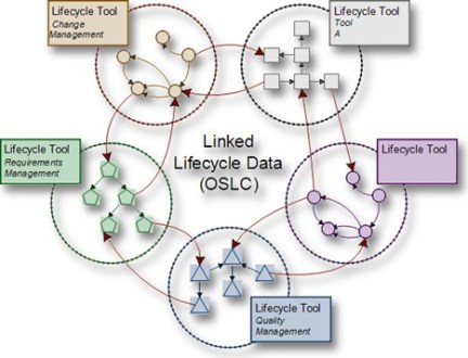
A new technology – based on Internet protocols – has emerged over the last few years; it is called Open Services for Lifecycle Collaboration (OSLC) (see Figure 3). OSLC is built upon the same technology as HTTP, which enables a remote view of information [6]. It operates in the same way as a Google search query in that Google doesn’t copy all queried information back to the user but only a view (a link to) the results. Using this same process, domain-specific engineering tools can be linked together.

In this process, individual design tools don’t need to link to a requirements-design data repository directly (as in a PLM suite) because the design tools know all about the relevant data. Instead, the OSLC-enabled tools share information by discretely providing a web-based list. The list allows the user to decide what level of detail about the change is needed.
OSLC tools will help capture the original system context work developed early in the lifecycle. Equally important, such tool technology will ensure that the system context grows and is available when changes occur throughout the development process. In this way, the systems engineer can be sure they are designing and building a system to solve the actual problem of the customer and end-user. The final product validation can be linked directly back to the original systems context, updated with any changes that occurred during development.
References:
[1] Handbook of Systems Engineering and Management, by Andrew P. Sage, William B. Rouse [2] System Engineering: Principles and Practices, by Kossiakoff and Sweet [3] https://en.wikipedia.org/wiki/System_context_diagram [4] The Engineering Design of Systems: Models and Methods, by Dennis M. Buede, [5] Augmenting System Change, Mentor Graphics whitepaper written by John Blyler, http://go.mentor.com/4u95t [6] https://en.wikipedia.org/wiki/Open_Services_for_Lifecycle_CollaborationOriginally Published: http://s3.mentor.com/public_documents/whitepaper/resources/mentorpaper_101451.pdf
Discover more from JB Systems Media and Tech
Subscribe to get the latest posts sent to your email.